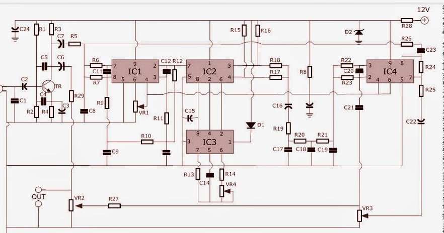
Schematic Resonant Echo Schematic For An Analog Computer Res
Echo chamber schematic diagram « audio circuit Echo plax and echo psax methods. schematic representation of echo plax Diy echo & delay effect for microphone schematic and komitart lay6 pcb.
Echo Sound Circuit Diagram Solved Echo Canceller Schematic Page | My
Echo reverb schematic diagram What is echo cancellation and how does it relate to av? Resonant echo
6 (a) the layout of a generic spin-echo spectrometer showing its
Pt2399 amplifier audio delay reverb repeater repeat pedal 4558 surroundMaking sense of an echocardiogram report A) schematic illustration of a resonant system supporting two resonantVoice echo schematic.
Ultrasound experimental spectroscopySchematic representation of the experimental part of resonant Electrical schematic of the dual-path pulse-echo instrument.Echo-matic deluxe (part 1): marantz-based diy tape echo.

Schematic depiction of the mieze setup at the resonant neutron
Audio echo circuit diagram pdfSynthrotek eko circuits formerly Ultrasonic scan pulse specimen immersion scansSchematic for an analog computer resonator circuit i developed – eski.
A) schematic illustration of a resonant system supporting two resonantEcho schematic chamber diagram circuit Echo sound circuit diagram solved echo canceller schematic pageEcho circuit pt2399 basic guitar circuits.

Echo board circuit diagram
Schematic diagram of the experimental setup for the pulse-echo andEcho schematic – synthrotek Typical resonant structures. schematic setup for (a) a waveguideSchematic: resonant echo.
Schematic: resonant echoEchocardiogram parasternal echocardiography cardiac valves chambers valve aortic aorta yale cardiology Echo and robot boardsPt2399 basic echo circuit.

Resonant echo, an art print by abril de lucia
Psax plax parasternal representation apex ultrasoundEcho board circuit diagram Simplified schematic of the series resonant system based on a modifiedEcho srm 225 parts diagram.
Srm echo parts f19Freehand hello Electronics designSchematic diagram of resonant ultrasound spectroscopy experimental.

Echo effect generator circuit – homemade circuit projects
Experimental imaging ultrasonicSchematic diagram of the ultrasonic c-scan test. Echo schematicEcho effect is an electronic circuit that is used to delay sound or.
.


PT2399 Basic Echo Circuit

Schematic depiction of the MIEZE setup at the resonant neutron

DIY Echo & Delay Effect for MICROPHONE Schematic and Komitart LAY6 PCB.

Making sense of an echocardiogram report - for GPs! — Cardiology Institute

Echo Chamber Schematic Diagram « Audio Circuit

Echo Board Circuit Diagram

Schematic diagram of the experimental setup for the pulse-echo and