Scr Power Inverter Circuit Diagram Inverter Phase Circuit Th
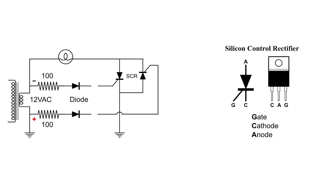
Inverter home wiring diagram pdf Study of fully controlled full wave rectifier using scr Scr principles and circuits
Scr Gate Firing Circuit Diagram - Circuit Diagram
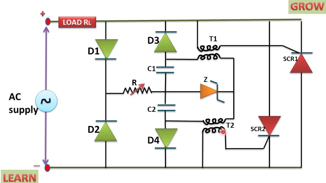
Scr as full wave rectifier circuit diagram Scr control circuit schematic Scr gate firing circuit diagram
Scr inverter
Scr circuits circuit wave power full ac off dc load principles figure nutsvoltsRectifier arduino wave full controlled circuit 220v bridge thyristor scr diagram simple project terminals connected grounded together Scr parallel inverter with power supplyCar battery charger based scr 2n3896.
Phase inverter scr electronics eevblog waveformsRegulator voltage scr circuits homemade capacitor Grid-tie inverter (gti) circuit using scr – homemade circuit projectsMini power inverter using scr, 300v 400hz.

Inverter circuit diagram mode 120 operation phase three bridge power formula shown below figure
Psim pspice inverter circuit power scr matlab simulink based electronics comparative circuits performance electronicsmakerInverter circuit diagram power medium Inverter parallel25khz using thyristor inverter welding machine circuit under.
120° mode inverter – circuit diagram, operation and formulaMatlab/simulink, psim & pspice comparative performance for power Three phase inverter circuit diagramInverter phase circuit thyristor diode conduction degree.

Medium power inverter circuit diagram
Scr inverter circuit diagram seekic basicScr power control circuit diagram Inverter circuit grid tie homemade scr using simplest diagram circuits gti scrs battery charger power latch will notSilicon controlled scr circuit diagram rectifier characteristics lab manual circuits computer devices electronic programming.
Ac to dc using 4 diode and 1 capacitor – full bridge rectifierInverter circuit schematic solar transformer project simple less watt diy 1000 hub electronics diagram 6 volt inverter circuit diagramScr power controller circuit diagram.

Scr inverter (thyristor h-bridge) schematics/working principle
Study of series inverter using scr3 phase inverter with scr Inverter: types, circuit diagram and applicationsScr power controller circuit diagram.
Inverter circuit diagram with feedbackInverter phase circuit three 120 degree mode conduction diagram dc dilip raja nov 13+ solar inverter schematic3 phase inverter wiring diagram.

Power control using scr
Charger battery scr car circuit based schematic inverter diagram reverse polaritySilicon-controlled rectifier(scr) characteristics electronic devices Inverter circuit 60hz power diagram build full schematics circuits diagrams inverters electronicScr voltage regulator circuit – homemade circuit projects.
Scr control power usingArduino 220v full wave controlled bridge rectifier Inverter circuit scr mini power diagram using 300v 400hz circuits transistor simple 500w full pure gr next productsBuild a 60hz power inverter circuit diagram.
Sg3525 inverter circuit diagram pdf
.
.


SCR INVERTER - Basic_Circuit - Circuit Diagram - SeekIC.com

Scr Power Controller Circuit Diagram

Three Phase Inverter Circuit Diagram - 120 Degree and 180 Degree

STUDY OF FULLY CONTROLLED FULL WAVE RECTIFIER USING SCR - Free

SCR Parallel Inverter with Power Supply
Power Control Using SCR - YouTube